
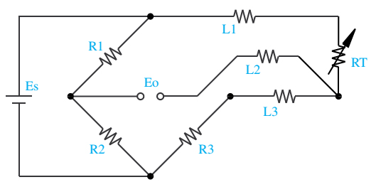
L1 and l3 carry the measuring current while l2 acts only as a potential lead. In this circuit there are three leads coming from the rtd instead of two.
![]()
Rtd Wiring Diagram 3 Wire Wiring Diagram And Schematic Diagram Images
V rtd = v meter (a) − v meter (b) once again, rtd resistance is calculated from the rtd.

3 wire rtd wiring diagram. There is a lead resistance in each arm of the bridge so that the resistance is cancelled out, so long as the two lead resistances are accurately the same. If the resistance is also measured through leads 2 and 3 (r2 + r3), we obtain the resistance of just the lead wires, and since all lead wire resistances. If three identical type wires are used and their lengths are equal, then r1 = r2 = r3.
3 wire rtd wiring diagram in this circuit there are three leads coming from the rtd instead of two. 3 wire rtd wiring diagram. L1 and l3 carry the measuring current while l2 acts only as a potential lead.
It shows the components of the circuit as streamlined forms as well as the power and also signal links between the tools. Since l1 and l3 are in separate arms of. Using this method the two leads to the sensor are on adjoining arms.
•allows complete utilization of the input range, no offset caused by the rtd itself. Diagrams, gallery of 3 wire thermocouple wiring diagram sample, circuit diagram wikipedia, 3 wire rtd wiring diagram wiring diagram pictures, how to wire three way switches part 1 ask the electrician, 3 wire switch diagram my wiring diagram, 3 way switch wiring electrical 101, 3 wire 220 outlet diagram best free wiring diagram, 3 speed fan. Insulate or terminate the unused white lead in a manner that prevents shorting to the ground.
•idac generates the sensor excitation and the reference voltage. In this uncompensated circuit, lead resistance l1 and l2 add directly to rt. On rtd pt100 3 wire wiring diagram.
•noise and drift of the ref voltage are correlated and therefore canceled. By measuring the resistance through leads 1, 2 and the resistance element, a total system resistance is measured (r1 + r2 + re ). You can connect only 4 rtd sensors to this module.
•voltage drop across the line resistance are compensated. In this circuit there are three leads coming from the rtd instead of two. Three wire rtd configuration a better wiring configuration is shown in figure 3.2.
In a 3 rtd there are 3 leads coming from the rtd sensor. L1 and l3 carry the measuring current while l2 acts only as a potential lead. This method assumes that wires 1,2 & 3 are all the same resistance.
Repairing electrical wiring, greater than every other household project is focused on. Rtd pt100 3 wire wiring diagram a beginner s guide to circuit diagrams. L1 and l3 carry the measuring current while l2 acts only as a potential lead.
An initial look at a circuit layout might be complicated yet if you could check out a subway map you can check out schematics. No current flows through it while the bridge is in balance.since l1 and l3 are in separate arms of the bridge,resistance is canceled. Essential tips for safe electrical repairs.
The 3 wire circuit works by measuring the resistance between #1 & #2 (r 1+2) and subtracting the resistance between #2 & #3 (r 2+3) which leaves just the resistance of the rtd bulb (r b). Although there is lead resistance in each leg of the bridge, the lead resistance is cancelled out from the measurement. We'll be using 1 platinum series meter, pr11 probe + a d20 meter with an omega calibr.
No current flows through it while the bridge is in balance.since l1 and l3 are in separate arms of the bridge,resistance is canceled. And rt is the rtd. No current flows through it while the bridge is in balance.
Here, the two leads of the sensor are on adjoining legs. 3 wire and apply power. 4 wire rtd wiring diagram.
A beginner's guide to circuit diagrams Here are tips how to wire your rtd to a meter by omega engineer, chet.

Rtd Wiring Diagram 3 Wire Wiring Diagram And Schematic Diagram Images

Rosemount 3 Wire Rtd Wiring Diagram Complete Wiring Schemas

3 Wire Rtd Wiring Diagram Gallery

3 Wire Rtd Wiring Diagram Wiring Diagram Networks

Rosemount 3 Wire Rtd Wiring Diagram Complete Wiring Schemas

Get 3 Wire Rtd Wiring Diagram Download
Rtd Pt100 3 Wire Wiring Diagram Free Wiring Diagram
3 Wire RTD Wiring a 3 Wire RTD

Rtd Pt100 3 Wire Wiring Diagram

[MK_9839] Three Wire Rtd Wiring Diagram For Schematic Wiring

Rtd Pt100 3 Wire Wiring Diagram

3 Wire Pt100 Sensor Wiring Diagram puertoricoinform

Get 3 Wire Rtd Wiring Diagram Download
3 Wire Rtd Wiring Diagram

Rtd Pt100 3 Wire Wiring Diagram Free Wiring Diagram

Rtd Pt100 3 Wire Wiring Diagram

3 Wire Rtd Wiring Diagram Gallery

Top 3 Wire Rtd Wiring Diagram Tips Switch

3 Wire Rtd Wiring Diagram Gallery