
Wiring is the same for both series. Duct, the unit communicates the condition to the honeywell silent knight control panel.

Best Relay Wiring Diagram 5 Pin Bosch Endearing Enchanting blurts.me Electrical circuit
Information kobelco sk200 wiring diagrams.

Sk relay wiring diagram. See more ideas about relay, diagram, electromagnet. The square relay pinout shows how the relay socket is configured for wiring. Connect the wires to the keypad according to the wiring diagram on page.
Find this and other arduino tutorials on arduinogetstarted.com. 595.22 x 842 pts (a4) (rotated 0 degrees). Also use a push to exit station.
Break wire run to provide supervision of connections. Refer to the wiring diagram (page 8) and ensure that the backlit jumper is properly set. This list covers single pole single throw (spst) relays, single pole double throw (spdt) relays, and double pole double throw (dpdt) relays.
With carl banas, joan fowler, stan francis, paul kligman. Connect each of the wires that will be used to operate the keypad according to the wiring diagram 8. The example relay diagrams below show how a relay works.
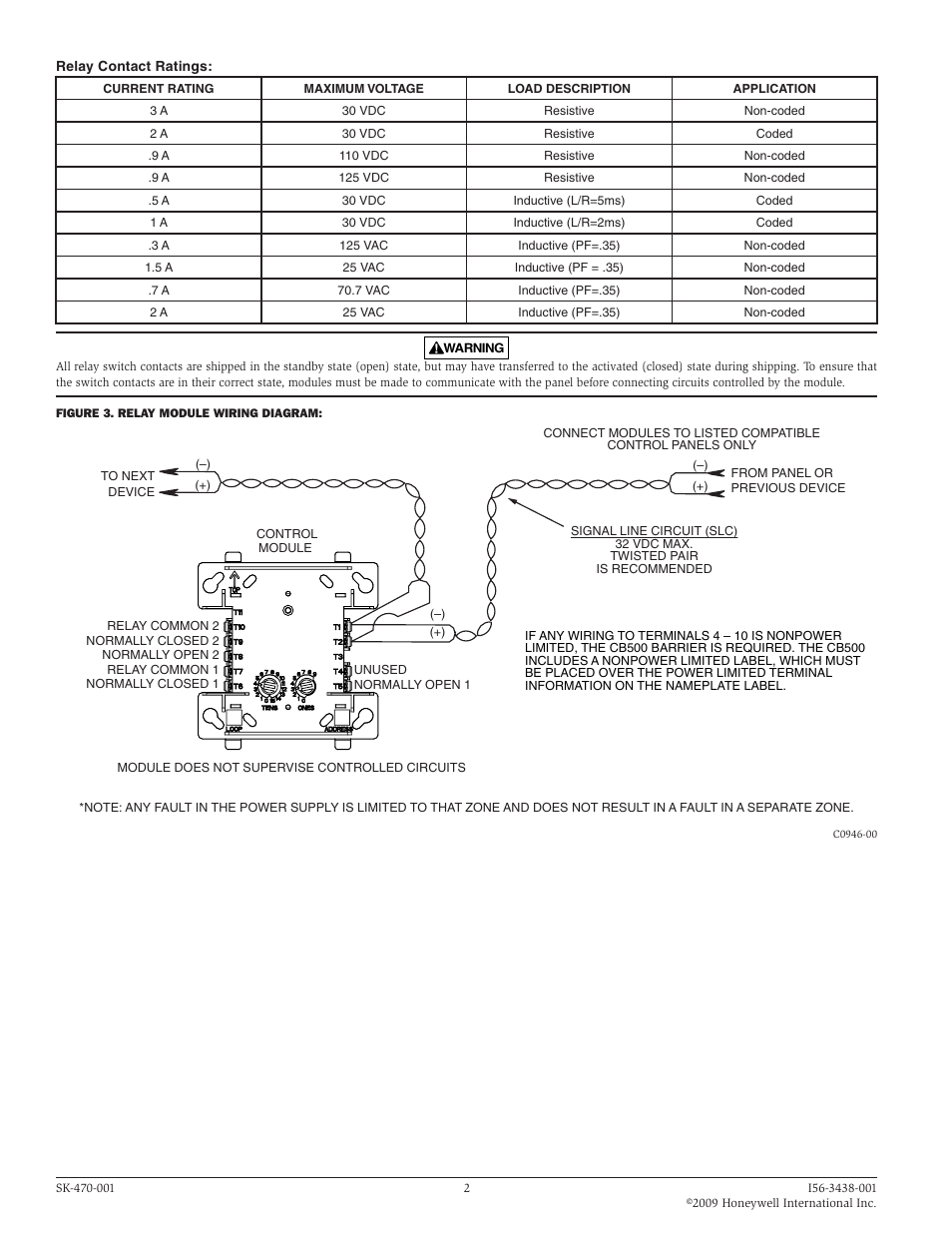
Each of the different types of relays have different configurations (as they have different numbers of pins). The module contains two isolated sets of form c contacts. They commonly use an electromagnet (coil) to operate their internal mechanical switching mechanism (contacts).
The panel, in turn, depending on programming and wiring, turns off fans, blowers, and other devices. A relay is an electrically operated switch. Fig 2 lucas with iso numbering 30/51 87 87a fig 1 85 86 jaguar xj6 s3 flasher indicators radio, aerial, boot.
Contact a distributor find a sales office support. Reattach the keypad to the mounting base. This manual can be viewed on any computer, as well as zoomed (take a closer look at the sample image for the most accurate information on the use of the book) and printed.
Sems screws for easy wiring. Substitute with a change over relay (part no rel7db available from us) and wire it in as per the relay schematic shown in fig 1. This page is for installers looking to do a basic installation and programming of the keypad.
Directed by jules bass, arthur rankin jr. Below are the diagrams for connecting the various types of relays. Leave room for the keypad wiring and wiring hole.
Note that the pin configuration is different on a standard iso relay than on the lucas delay module, fig 2. One relay required for each circuit. This page is for installers looking to do a basic installation and programming of the keypad.
Black red brown orange yellow green pink aqua. 3 pin xlr connectors are standard amongst line level and mic level audio applications. 12 volt 4 pin relay wiring diagrams within 12v 5 pin relay wiring diagram, image size 983 x 612 px, image source :
Each channel can be independently programmed to operate in a diff erent function, depending on the user's app lication. The relay contains two isolated sets of form c contacts, which operate as a dpdt switch. 5.5 kw magnetic contactor size (mm) type sk06 sk09 sk12 sk18 sk22 sk32 thermal overload relay size (mm) type tk12 tk25 tk26 magnetic contactor and thermal overload relay sk series supporting the market for motor drive circuits such as.
When a relay contact is open, this will switch power on for a circuit when the coil is activated. The 5 pin plug on the machine has two blacks one brown one blue and a greenyellow wires. Find a product partner popular resources/quicklinks.
Run the wire through the wall or conduit to the keypad location, then run the wire through the hole on the back of the keypad. Some control panels have relay built in and do not require external wiring. This handbook has 5496780 bytes with 27 pages presented to you in pdf format page size:
The relay contains two isolated sets of form c contacts, which operate as a dpdt. Learn how to use relay with arduino, how relay works, how to connect relay to arduino, how to code for relay, how to program arduino step by step.

ELECTRIC Fog Light Relays Electric car engine, Electricity, Electric cars

Aux Light Wiring Diagram 5 Wire Relay Wiring diagram, Electrical wiring diagram, Trailer light

[SK_8481] Cnc Spindle Wiring Diagram Schematic Wiring

Pin on Wiring Horness Clean Wiring job

Mini Contactor Wiring Diagram

4 Pin Relay Wiring Diagram Lights Electricity, Electrical diagram, Automotive electrical
Diagram by Akita Your Diagram Source from Akita. Electrical circuit diagram, Relay

Basic Relay Connections Electric car engine, Car mechanic, Electrical diagram

Beautiful 12 Volt Relay Wiring Diagram Symbols diagrams digramssample diagramimages

Pin on a
SilentKnight SKRelay Addressable Relay Module User Manual Page 2 / 2
Kobelco Sk210 Wiring


Best Relay Wiring Diagram 5 Pin Wiring Diagram Bosch 5 Pin Relay Gallery Image Electrical

Images Of Wiring Diagram For Horn Relay Harley Davidson A New Bosch Car horn, Motorcycle

Pin en Conexiones electricas

Pin by Abdullah Afif on Cars Electrical . كهرباء السياراة Car horn, Electrical wiring diagram

Led Light Bar Wiring Diagram Pretty How Wire Without Relay Present Within Automotive

please help how to install 4 pin relay with horns. Relay, Installation, Beach buggy

Pictures Wiring Diagram Horn Relay HORN RELAY Simple Throughout Bosch For Automotive